
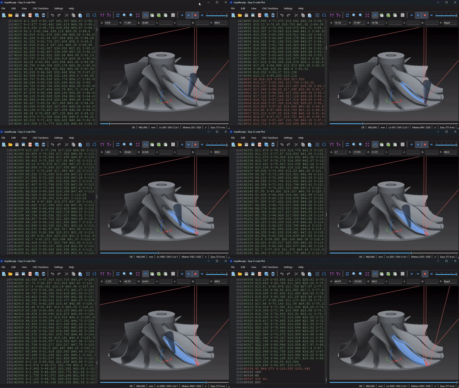
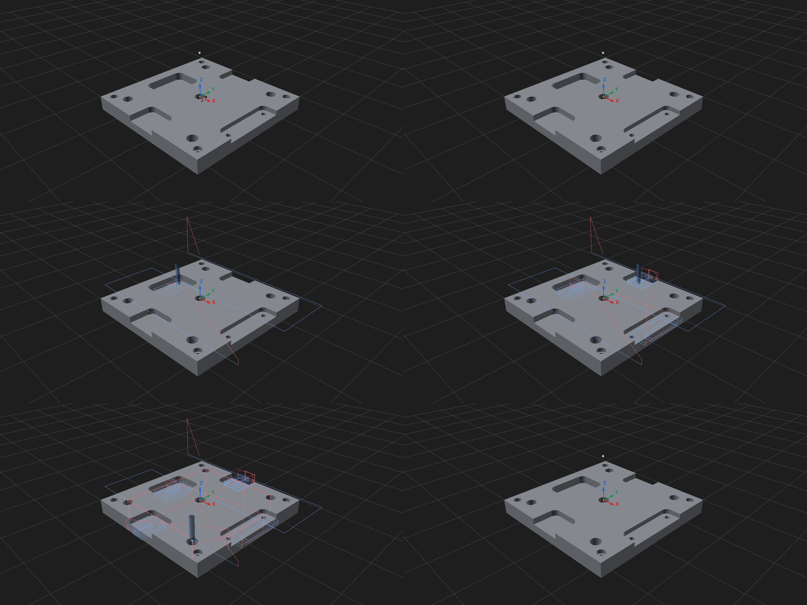
Toolpath playback and STL models
Step through tool motions and navigate to the corresponding source line. Load ASCII or binary STL models; position, rotate, copy and section them in the same scene.
Windows / Linux · GUI / CLI
Edit turning and milling programs, calculate toolpaths and inspect tool motion in a 3D scene. Supports FANUC and a subset of SINUMERIK 840D commands.
Linux builds are also available on the release page.
| Operation | Type A | Type B |
|---|---|---|
| Rapid | G00 | G00 |
| Linear | G01 | G01 |
| Arc CW | G02 | G02 |
| Arc CCW | G03 | G03 |
| Dwell | G04 | G04 |
| Thread cutting | G32 | G33 |
| Coordinate system / spindle clamp | G50 | G92 |
| Finish cycle | G70 | G70 |
| Rough turning | G71 | G71 |
| Rough facing | G72 | G72 |
| Pattern repeating | G73 | G73 |
| Face peck drilling | G74 | G74 |
| OD/ID grooving | G75 | G75 |
| Multiple threading | G76 | G76 |
| Turning canned cycle | G90 | G77 |
| Threading canned cycle | G92 | G78 |
| Facing canned cycle | G94 | G79 |
| Feed per minute | G98 | G94 |
| Feed per revolution | G99 | G95 |
| Type A | Type B | Purpose in the kernel |
|---|---|---|
| G70 | G70 | P-Q finishing contour |
| G71 | G71 | Longitudinal roughing |
| G72 | G72 | Facing roughing |
| G73 | G73 | Pattern-repeat roughing |
| G74 | G74 | Z peck / face grooving |
| G75 | G75 | X peck / radial grooving |
| G76 | G76 | Two-line multipass threading |
| G83 | G83 | Axial peck drilling |
| G84 | G84 | Axial tapping |
| G90 | G77 | Modal longitudinal turning cycle |
| G92 | G78 | Modal threading cycle |
| G94 | G79 | Modal facing cycle |
| Cycle | Description |
|---|---|
G70 |
The finish path is based on the nominal P-Q profile, not the roughing-offset profile used by G71/G72/G73. If tool-nose compensation is active and can be verified, the finishing contour uses the compensated profile. After the finish group, the cycle returns to the saved call position using the project's deterministic turning return order. |
G71 |
The common two-line FANUC form is modeled: The first line captures rough depth and retract. The second line supplies the P-Q profile, finishing allowances and feed. |
G72 |
G72 uses the same P-Q profile infrastructure as G71 but performs facing roughing in Z planes. Typical two-line form: The first line captures axial depth and retract. The second line references the profile and finishing allowances. |
G73 |
G73 is implemented as repeated shifted copies of the roughing profile. The first line captures the total U/W pattern displacement and the R pass count. The second line provides P/Q, finish allowances and feed. The signs of programmed U/W are preserved. The cycle does not infer displacement direction from where the tool happened to approach the contour. |
G74 |
G74 supports Z-direction peck behavior and face-grooving style repetition. A first block containing R alone can establish the retract distance. The executing block can use X/U and Z/W plus P/Q/R/F parameters. If no X target is supplied, G74 can operate as a drilling-style Z peck at the current X. When X repetition is requested, P controls the X step and Q controls Z peck depth. The cycle returns to its saved start using an explicit Z-first return order. |
G75 |
G75 performs X-direction peck/radial grooving. P controls the radial peck step. Q can repeat grooves along Z. If Q is omitted, a programmed Z/W selects one groove location rather than being treated as an invalid zero-step repetition. The R value from the setup block controls retract distance, and the executing-block R value is handled as the bottom allowance where applicable. |
G76 |
The modeled form is FANUC-style two-line G76: The first block stores:
The second block supplies:
|
G83 |
G83 is an axial Z drilling cycle.
|
G84 |
G84 is an axial tapping cycle. The downstroke and return are synchronized feed motions; the return is not represented as a rapid move. |
G90 |
Yes. G90 establishes a longitudinal rectangular turning cycle. Subsequent X/U-only blocks can continue the active cycle at new diameters until cancellation by another explicit motion/cycle code. |
G92 |
Example: The initial G92 establishes the thread end and lead. Subsequent X/U-only blocks continue the active G92 cycle with new depths until another explicit motion/cycle mode cancels it. Each pass expands to approach, synchronized longitudinal cutting, retract and return primitives. |
G94 |
Yes. G94 establishes a facing rectangular cycle. Subsequent Z/W-only blocks can continue the active cycle at new face positions until cancellation. |
G71 Type II supports pocketed profiles conservatively. G72 Type II rejects multiple disjoint spans in one facing plane (UNSUPPORTED_G72_TYPE_II_SPANS). G76 supports tool angles 0°, 29°, 30°, 55°, 60° and 80°; other angles produce UNSUPPORTED_G76_TOOL_ANGLE.
| G code | Function in the kernel |
|---|---|
| G00 | Rapid positioning |
| G01 | Linear interpolation |
| G02 / G03 | Clockwise / counterclockwise circular interpolation |
| G04 | Dwell signal; no spatial motion |
| G10 |
Program WCS offsets (L2, L20)
|
| G15 / G16 | Cancel / enable polar coordinate programming |
| G17 / G18 / G19 | Select XY / XZ / YZ plane |
| G20 / G21 | Inch / millimetre input units |
| G28 | Reference return using the configured home |
| G40 / G41 / G42 | Cancel / left / right cutter-radius compensation |
| G43 / G49 | Track / cancel tool-length state; G43 does not apply H geometry to the plotted path |
| G43.4 | Continuous TCP linear and rotary motion for the enabled angled AC/BC table profiles; circular rotary arcs and combination with G68.2 are unsupported |
| G50 / G51 | Cancel / enable coordinate scaling |
| G52 | Local coordinate shift |
| G53 | Non-modal machine-coordinate motion |
| G54–G59 | Select work coordinate system |
| G54.1 P1–P99 | Parsed and selected; the GUI has no offset setting, so the offset is zero unless the program sets it with G10 L20 |
| G65 | Call a Macro B program |
| G68 / G69 | Enable / cancel coordinate rotation |
| G68.2 / G53.1 |
Tilted working plane / tool-axis orientation (3+2,
fanuc_mill with two-axis table-table,
head-head or head-table kinematics)
|
| G73 | High-speed peck drilling cycle |
| G80 | Cancel canned cycle |
| G81 | Drilling cycle |
| G82 | Drilling cycle with dwell |
| G83 | Full-retract peck drilling cycle |
| G84 | Tapping cycle |
| G85 | Boring cycle with feed return |
| G86 | Boring cycle with spindle-stop signal |
| G90 / G91 | Absolute / incremental programming |
| G94 / G95 | Feed per minute / feed per revolution |
| G98 / G99 | Return to initial / R plane in canned cycles |
| M code | Function in the kernel |
|---|---|
| M00 / M01 | Stop / optional-stop signal |
| M02 / M30 | End program |
| M03 / M04 / M05 | Spindle clockwise / counterclockwise / stop signals |
| M06 | Tool-change event for the selected T number |
| M07 | Recognized; no machine-specific coolant action is modeled |
| M08 / M09 | Coolant on / off signals |
| M19 | Spindle-orientation signal; S on this block is an angle, not spindle RPM |
| M29 | Prepare rigid tapping; S on this block sets spindle RPM for the following G84 |
| M98 / M99 | Call / return from subprogram |
| Command | Description |
|---|---|
G73 / G83 |
G73 is high-speed peck drilling with short intermediate retract behavior. G83 uses the full-retract drilling behavior modeled by the common drilling layer. |
G82 |
G82 includes its dwell semantics, but dwell itself does not create spatial geometry. |
G84 |
G84 tapping returns from depth as synchronized feed motion rather than rapid motion. |
G86 |
The cycle models spindle-stop semantics together with its drilling motion/return behavior. |
G98 / G99 |
For milling canned cycles, G98/G99 select cycle return behavior. They are not the turning feed-mode meanings of G98/G99. |
| ISO-M function | Support and limitations |
|---|---|
| G290 / G291 | Standalone blocks select native / ISO-M mode. MPF/SPF execution starts in native mode. |
| XYZ / G90 / G91 | Three-axis positioning, including incremental positioning. Rotary axes and TCP are unsupported. |
| G2 / G3 / IJK | ISO-M uses relative arc centers; native uses absolute centers. Each arc follows its active controller mode. |
| G54 P1–P48 | Extended work offsets. Source G54.1 and other decimal G codes are rejected. |
| G50 / G51 | Coordinate scaling; G51 uses P/1000 weighting. |
| G68 / G69 | Standalone 2D rotation with G90, center axes of the active plane and R. I/J/K, incremental-angle and 3D-vector forms are rejected. |
| Cycles and units | Common integer milling G codes, unit selection, coordinate systems and selected canned cycles are accepted within the ISO-M subset. |
| Macro B / ISO-T | Macro B program flow and ISO Dialect T are unsupported. Unsupported ISO functions produce diagnostics. |
| Native function | Current behavior |
|---|---|
G0/G1, G2/G3,
G17/G18/G19
|
XYZ positioning, linear moves and arcs in the selected
plane; CR= radius arcs, including negative
radius for a major arc
|
G90/G91, G54–G59,
G710
|
Absolute/incremental coordinates, work offsets and metric units |
G40/G41/G42 |
Modeled cutter-radius compensation using the configured tool |
T, M6, D0/D1,
S, basic M codes
|
Tool change, modeled cutting-edge selection/cancellation, spindle and coolant signals; controller-specific offset tables are not simulated |
G0 SUPA ... D0 |
Nonmodal machine-coordinate positioning;
SUPA Z0 means machine zero, independently of
the configured home Z
|
G64, MSG(...),
WORKPIECE(...), ; comments
|
Path-control/display metadata and comments; no blending or stock geometry is generated from these declarations |
MCALL CYCLE81/82/83/84(...) |
Modal Z drilling/tapping in G17/G40,
triggered by subsequent XY blocks; bare
MCALL cancels the cycle
|
CYCLE81/82 |
Drilling and rapid return, with modeled seconds-based
dwell for CYCLE82; safety plane is
RFP + SDIS, return plane is RTP
|
CYCLE83 |
Modeled first depth, amount degression, minimum peck depth, chip-breaking/full-retract options and reentry clearance |
CYCLE84 |
Single-pass metric right-hand tapping in G94:
explicit positive PIT,
_PITA=0/1, SDAC=3, Z axis and
positive SST equal to programmed
S; equal SST1 or zero/omitted.
Feed = pitch × rpm; feed withdrawal to
RFP+SDIS, rapid return to RTP,
optional dwell in seconds
|
CYCLE800() |
Empty reset accepted only when no rotary frame is active; parameterized tilted-plane transformation is not implemented |
Three-axis XYZ only. Parameterized CYCLE800, TRAORI/TRAFOOF, rotary motion and arbitrary Siemens subprogram calls are unsupported. R parameters support numeric assignments and direct references; arithmetic expressions and Siemens control flow are unsupported. CYCLE84 is limited to single-pass metric right-hand tapping; deep tapping, left-hand tapping and unequal entry/withdrawal speeds produce diagnostics.
Step through tool motions and navigate to the corresponding source line. Load ASCII or binary STL models; position, rotate, copy and section them in the same scene.
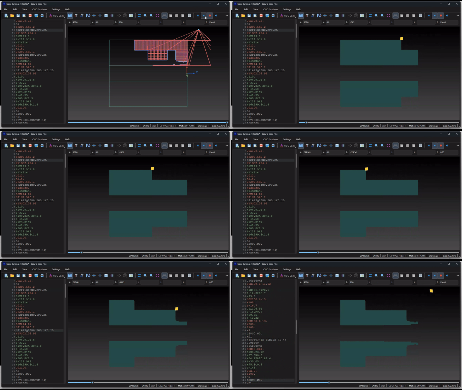
Material removal is calculated from tool geometry and the executed toolpath. Supports external, internal and face turning, grooves and thread profiles. Playback can move forward and backward.
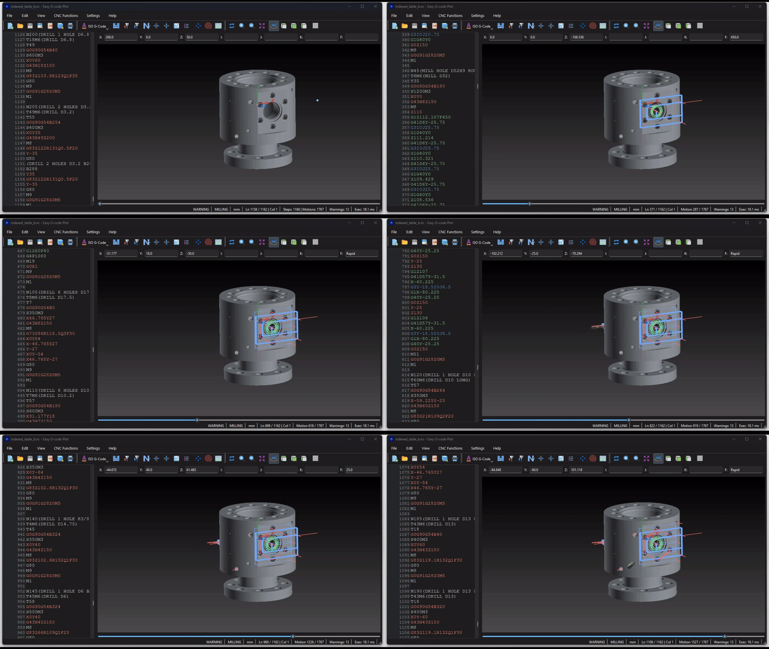
A/B/C table profiles, indexed 3+2 machining with G68.2/G53.1 and a supported subset of G43.4 TCP motion. The selected kinematics profile determines the displayed toolpath.
Syntax highlighting, search and replace, block numbering, block skip, snippets, tool-change navigation and macro variable inspection.
Turning and milling tool geometry, a saved SQLite library and a separate tool set for the current program.
Circular and rectangular hole patterns and pockets with a preview.
The kernel evaluates program flow, variables, cycles, coordinate systems and tool compensation. The resulting moves are used by the 3D view, playback, statistics and export. The desktop interface and CLI use the same calculation kernel.
When an unsupported command affects the tool position, the kernel reports a diagnostic and marks the result as incomplete. The application models toolpath geometry; it does not simulate all physical processes of a CNC machine.
Full Program preserves the source structure within the supported export scope. Expanded Execution exports calculated moves after expanding cycles, macros and subprograms.
Export calculated toolpath geometry to DXF or motion data to Plot Data.
parse, trace, analyze and export process individual programs. batch and batch-export process directory trees and produce reports.
Supported commands, settings, limitations and usage examples.